SR Flip Flop

Working Principle of SR Flip Flop
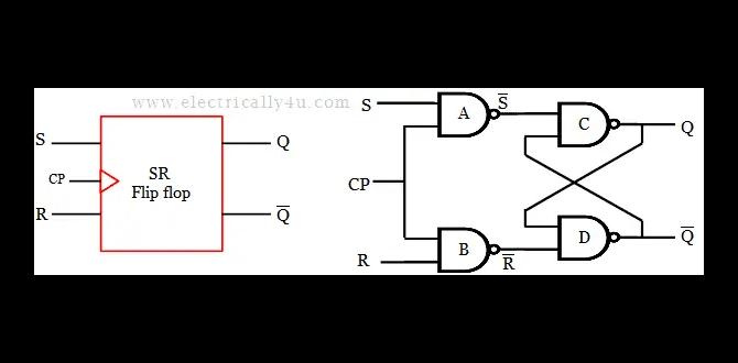
The SR flip flop stands for Set-Reset flip flop. It consists of two inputs: the S (Set) input and the R (Reset) input. The outputs of the flip flop are denoted as Q and Q’. When both inputs are low, i.e., S = R = 0, the flip flop maintains its previous state. When both inputs are high, i.e., S = R = 1, the flip flop enters an indeterminate state. Other combinations of input values produce predictable outcomes, allowing for the storage and control of binary data.Truth Table of SR Flip Flop
The truth table for an SR flip flop is as follows:| S | R | Q | Q’ |
|---|---|---|---|
| 0 | 0 | Q(t) | Q'(t) |
| 0 | 1 | 0 | 1 |
| 1 | 0 | 1 | 0 |
| 1 | 1 | Q(t-1) | Q'(t-1) |
Characteristics of SR Flip Flop
- An SR flip flop is asynchronous, meaning the outputs can change immediately upon receiving new inputs.
- It has two stable states: Set (Q = 1, Q’ = 0) and Reset (Q = 0, Q’ = 1).
- When S = R = 1, the flip flop enters an indeterminate state.
- SR flip flops can be constructed using NAND or NOR gates.
JK Flip Flop

Working Principle of JK Flip Flop
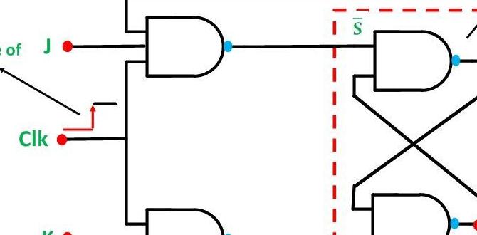
The JK flip flop combines the best features of both SR and T flip flops. It has two inputs: J (Jack) and K (Kangaroo). The outputs are Q and Q’. The JK flip flop is similar to the SR flip flop, but it avoids the indeterminate state when both inputs are high by creating a toggle effect. When both J and K inputs are low, the flip flop maintains its previous state. The outputs change according to the inputs when either J or K is high.Truth Table of JK Flip Flop
The truth table for a JK flip flop is as follows:| J | K | Q | Q’ |
|---|---|---|---|
| 0 | 0 | Q(t) | Q'(t) |
| 0 | 1 | 0 | 1 |
| 1 | 0 | 1 | 0 |
| 1 | 1 | Q'(t-1) | Q(t-1) |
Characteristics of JK Flip Flop
- A JK flip flop is a versatile flip flop that can function as both a set/reset flip flop and a toggle flip flop.
- It has three stable states: Set (J = 1, K = 0), Reset (J = 0, K = 1), and Toggle (J = 1, K = 1).
- When J = K = 0, the flip flop maintains its previous state.
- JK flip flops can be constructed using NAND or NOR gates.
D Flip Flop
Working Principle of D Flip Flop
The D flip flop, also known as the Data flip flop, is the simplest type of flip flop. It has a single input D (Data) and two outputs Q and Q’. The flip flop stores the value of the D input and maintains it until a new value is provided.Truth Table of D Flip Flop
The truth table for a D flip flop is as follows:| D | Q | Q’ |
|---|---|---|
| 0 | Q(t) | Q'(t) |
| 1 | 1 | 0 |
Characteristics of D Flip Flop
- A D flip flop synchronizes the input with a clock signal, allowing for proper data storage and retrieval.
- It has two stable states: 0 (Q = 0, Q’ = 1) and 1 (Q = 1, Q’ = 0).
- When the clock signal changes, the D input gets latched and reflected in the outputs.
- D flip flops can be constructed using logic gates such as NAND, NOR, or with dedicated D flip flop ICs.
T Flip Flop

Working Principle of T Flip Flop
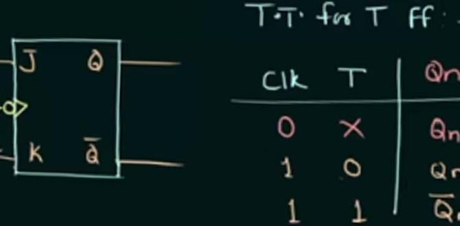
The T flip flop, or Toggle flip flop, is the simplest form of a counter. It has a single input, T (Toggle), and two outputs, Q and Q’. The flip flop changes its state based on the rising edge (transition from low to high) of the clock signal. When T is low, the flip flop maintains its previous state. When T is high, the flip flop toggles its state – from 0 to 1 or from 1 to 0.Truth Table of T Flip Flop
The truth table for a T flip flop is as follows:| T | Q | Q’ |
|---|---|---|
| 0 | Q(t) | Q'(t) |
| 1 | Q'(t-1) | Q(t-1) |
Characteristics of T Flip Flop
- A T flip flop is widely used in applications where toggling between two states is required, such as frequency division circuits.
- It has two stable states: 0 (Q = 0, Q’ = 1) and 1 (Q = 1, Q’ = 0).
- When the rising edge of the clock signal occurs, the T input is reflected in the outputs.
- T flip flops can be constructed using logic gates such as NAND, NOR, or with dedicated T flip flop ICs.
Conclusion
Flip flops are crucial building blocks in digital systems, enabling the storage and control of binary data. Understanding the different types of flip flops, including SR, JK, D, and T flip flops, allows for the proper design and implementation of digital circuits. Each flip flop type has its own working principle, truth table, and characteristics, providing different functionalities and capabilities. By utilizing these flip flop types effectively, complex digital systems can be designed and operated efficiently.FAQs

Q: Can flip flops be used for memory storage?
A: Yes, flip flops are commonly used for memory storage in digital systems. They can store binary data and retain it until new data is provided.
Q: How can I construct a flip flop using logic gates?
A: Flip flops can be constructed using various logic gates such as NAND, NOR, or using dedicated flip flop ICs that provide predefined functionality.
Q: Are flip flops only used in digital circuits?
A: Yes, flip flops are primarily used in digital circuits to store and control binary data. They are essential components in memory units, counters, and sequential circuits.
Q: Can flip flops be cascaded together?
A: Yes, flip flops can be cascaded together to create larger memory units or to build complex sequential circuits. This allows for the storage and manipulation of larger amounts of data.
Q: What is the advantage of using a JK flip flop over an SR flip flop?
A: The JK flip flop eliminates the indeterminate state that can occur in an SR flip flop when both inputs are high. It provides additional functionality by allowing toggle operations, making it more versatile in various applications.